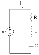
Circuit Theory/RLC Circuits
Template:Circuit Theory/Page Template:Wikipedia
Series RLC Circuit

Second Order Differential Equation
The characteristic equation is
Where
When
- The equation only has one real root .
- The solution for
- The I - t curve would look like
When
- The equation has two real root .
- The solution for
- The I - t curve would look like
When
- The equation has two complex root .
- The solution for
- The I - t curve would look like
Damping Factor
The damping factor is the amount by which the oscillations of a circuit gradually decrease over time. We define the damping ratio to be:
| Circuit Type | Series RLC | Parallel RLC |
|---|---|---|
| Damping Factor | ||
| Resonance Frequency |
Compare The Damping factor with The Resonance Frequency give rise to different types of circuits: Overdamped, Underdamped, and Critically Damped.
Bandwidth
For series RLC circuit:
For Parallel RLC circuit:
Quality Factor
For Series RLC circuit:
For Parallel RLC circuit:
Stability
Because inductors and capacitors act differently to different inputs, there is some potential for the circuit response to approach infinity when subjected to certain types and amplitudes of inputs. When the output of a circuit approaches infinity, the circuit is said to be unstable. Unstable circuits can actually be dangerous, as unstable elements overheat, and potentially rupture.
A circuit is considered to be stable when a "well-behaved" input produces a "well-behaved" output response. We use the term "Well-Behaved" differently for each application, but generally, we mean "Well-Behaved" to mean a finite and controllable quantity.
Resonance
With R = 0
When R = 0 , the circuit reduces to a series LC circuit. When the circuit is in resonance, the circuit will vibrate at the resonant frequency.
The circuit vibrates and may produce a standing wave, depending on the frequency of the driver, the wavelength of the oscillating wave and the geometry of the circuit.
With R ≠ 0
When R ≠ 0 and the circuit operates in resonance .
- The frequency dependent components L , C cancel out ie ZL - ZC = 0 so that the total impedance of the circuit is
- The current of the circuit is
- The Operating Frequency is
If the current is halved by doubling the value of resistance then
- Circuit will be stable over the range of frequencies from
The circuit has the capability to select bandwidth where the circuit is stable . Therefore, it is best suited for Tuned Resonance Select Bandwidth Filter
Once using L or C to tune circuit into resonance at resonance frequency The current is at its maximum value . Reduce current above circuit will respond to narrower bandwidth than . Reduce current below circuit will respond to wider bandwidth than .
Conclusion
| Circuit | General | Series RLC | Parallel RLC |
|---|---|---|---|
| Circuit |  |
 | |
| Impedance | Z | ||
| Roots | λ | λ = | λ = |
| I(t) | Aeλ1t + Beλ2t | Aeλ1t + Beλ2t | Aeλ1t + Beλ2t |
| Damping Factor | |||
| Resonant Frequency | |||
| Band Width | |||
| Quality factor |