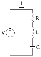
Electronics Handbook/Circuits/RLC Series
Jump to navigation
Jump to search
RLC Series

Circuit Analysis
Circuit's Impedance
Natural Response
- ±
- . There is only one real root,
- s = -αt
- =
- , There are two real roots,
- ±
- =
- , There are two complex roots,
- ±
- =
Current change with time depends on the value of R L and C
- . Dòng điện giảm dần theo hàm số mủ của e
- . Dòng điện giảm đến một giá trị âm rồi tăng đến một giá trị dương
- . Mạch điện có có Dòng Điện của Sóng Sin giảm dần theo theo thời gian
Resonance Response
At resonance
- .
Analyze the circuit at
- . Capacitor opens circuit
- . Inductor opens circuit
- .
At resonance, series RLC is capable of select a bandwidth of frequencies where voltage is stable does not change with frequencies. Therefore, can be used as Tuned - Resonance Band Pas Selected Filter
Summary
- The natural Response of the RLC series is a second order differential equation of current
Depends on the value of Resistance the equation has
One Real Root Two Real Roots Two Complex Roots One real root
Two real roots
- At Resonance when all the frequency dependent components cancel out RLC series behaves like Tuned Resonance Selected Band Pass Filter